

Short answer
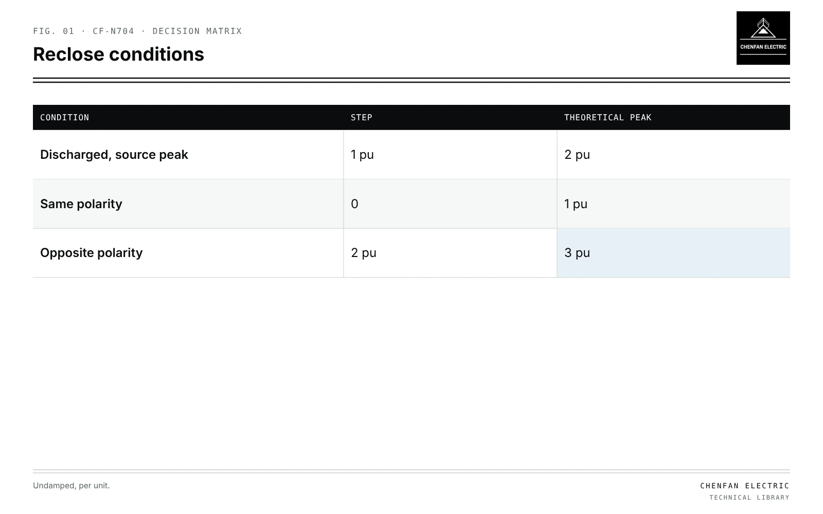
Capacitor residual charge reclosing duty is more severe than energising a discharged bank. A capacitor bank is disconnected when its current passes through zero, which for a capacitive load is when its voltage is at peak. The bank therefore holds a trapped charge near 1 per unit. If the bank is reclosed while still charged and the source voltage is at the opposite peak, the voltage step is about 2 per unit and the theoretical overshoot reaches about 3 per unit, with inrush current roughly twice that of a discharged bank. Discharge devices reduce trapped voltage over time, but whether and when reclosing is permitted must come from the bank and switch manufacturers’ stated conditions, not assumed. Recorded waveforms of capacitor voltage at opening and reclosing support verification. No operational waiting times or discharge steps are given here.
Why charge is trapped
| Condition | Step | Theoretical peak |
|---|---|---|
| Discharged, source peak | 1 pu | 2 pu |
| Same polarity | 0 | 1 pu |
| Opposite polarity | 2 pu | 3 pu |
Capacitive current leads voltage by 90°. The switch interrupts at current zero, when voltage is at its peak. The bank stays charged at that voltage, decaying only through its discharge device and leakage.
Reclosing onto trapped charge
Illustrative example. Bank trapped at +1.0 pu; reclose when the source is at −1.0 pu; damping neglected. Values chosen for demonstration.
ΔU = −1.0 − (+1.0) = −2.0 pu
Uovershoot ≈ −1.0 + (−2.0) = −3.0 pu
The inrush current is proportional to the voltage step, so it is about twice that of energising a discharged bank at a source peak. Back-to-back conditions multiply the effect; see back-to-back capacitor switching near a transformer bus.
| Condition at reclose | Voltage step | Theoretical peak |
|---|---|---|
| Discharged, source at peak | 1 pu | 2 pu |
| Charged +1, source at +1 | 0 | 1 pu |
| Charged +1, source at −1 | 2 pu | 3 pu |
Damping, arrester operation and switch prestrike reduce real values.
Discharge devices versus permission
- Discharge devices (resistors, discharge reactors or VTs) reduce trapped voltage with a time constant stated by the manufacturer and the capacitor standard.
- Switching permission depends on the switch’s capacitive making capability, the bank’s overvoltage withstand and the protection scheme.
- Automatic reclosing on feeders with capacitor banks needs coordination so banks are not reclosed charged; see recloser shot sequences.
The relevant times and voltages come from manufacturer data and standards; this article does not state them as instructions.
Waveforms for verification
- Capacitor voltage per phase at opening, showing trapped level.
- Decay over time until reclose.
- Voltage and current at reclose, showing step and overshoot.
- Switch timing relative to source voltage.
Manufacturers can confirm duty from such records. Pre-insertion and controlled switching reduce severity; see capacitor bank energization with pre-insertion devices.
What this article does not cover
It gives no waiting times or discharge procedures to follow; these must come from manufacturer instructions and site safety rules.
Where this reasoning stops. Undamped values are upper bounds; real duty needs transient simulation or measurement.
Practical takeaway
Treat a recently disconnected capacitor bank as charged, block reclosing until manufacturer-stated conditions are met, and verify duty with waveforms of trapped voltage and reclose transients.
Reference framework
- IEEE 18, Standard for shunt power capacitors.
- IEC 60871-1, Shunt capacitors for a.c. power systems having a rated voltage above 1 000 V.