


Transformer Core Engineering Notes · CF-N204
Dividing a winding conductor into parallel strands does not guarantee equal current. Each branch has its own resistance, induced voltage and leakage-flux linkage. Equal copper area is therefore only one starting condition. A useful review traces the complete paths—from the winding positions to the joints—before treating the total current as evenly divided.
Start with a deliberately simple circuit
For two purely resistive parallel branches at the same terminal voltage, current is inversely proportional to branch resistance. If one branch is 10% more resistive, its current is lower, not equal. This illustrates sensitivity to joints and length, but it is not a transformer-winding loss model. Real strands also link time-varying leakage flux; differences in induced voltage can drive circulating current. The electromagnetic model must include those effects where they are significant.
Position can matter as much as length
Strands occupying different radial or axial positions can experience different fields. Transposition exchanges positions to reduce systematic differences in exposure, but its effectiveness depends on the actual arrangement. A statement that conductors are transposed should identify the scheme and where it applies. Lead sections outside the transposed winding may remain unequal. Ask whether the analysis includes these sections, rather than assuming that one transposition feature balances every part of the circuit.
Separate inspection from performance prediction
Incoming conductor dimensions and finished joint resistance are valuable checks, but neither alone proves acceptable AC current distribution. Review the connection drawing, conductor-position schedule and additional-loss calculation together. Where measurements are proposed, identify what they can resolve and the load condition used. A total winding resistance measurement may hide opposing branch deviations. Local temperature evidence can also be incomplete if sensors are remote from the branch or joint of interest.
Avoid fixing one imbalance by creating another
Changing joint geometry to equalize resistance can alter lead spacing, support or field exposure. Likewise, adding more parallel strands changes insulation content and connection count. Assess these changes together before release. The procurement question is not simply how many strands are present, but whether the chosen branch arrangement has a documented loss and thermal basis. Request a revision-linked explanation whenever conductor count, transposition or terminal routing changes after design approval.
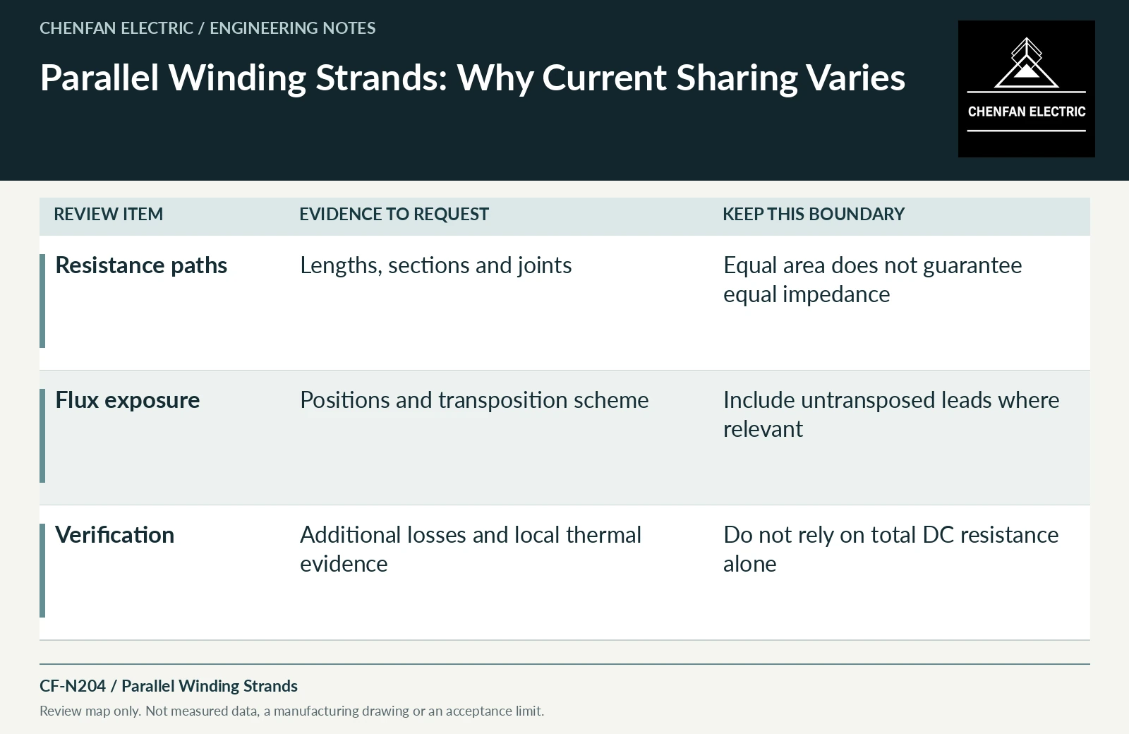
| Review item | Evidence to request | Boundary to preserve |
|---|---|---|
| Resistance paths | Lengths, sections and joints | Equal area does not guarantee equal impedance |
| Flux exposure | Positions and transposition scheme | Include untransposed leads where relevant |
| Verification | Additional losses and local thermal evidence | Do not rely on total DC resistance alone |
References and scope
- Continuously Transposed Cable (CTC)Manufacturer technical page · Strand arrangement and transposition concept; supplied dimensions and restrictions require the current product specification.
- IEC 60076-5:2006 — Ability to withstand short circuitPublic standard abstract · Thermal and dynamic short-circuit capability; calculation and verification apply to the actual design.
- IEC 60076-2:2011 — Temperature rise for liquid-immersed transformersPublic standard abstract · Temperature-rise requirements, cooling identification and the distinction between test conditions and installed duty.