

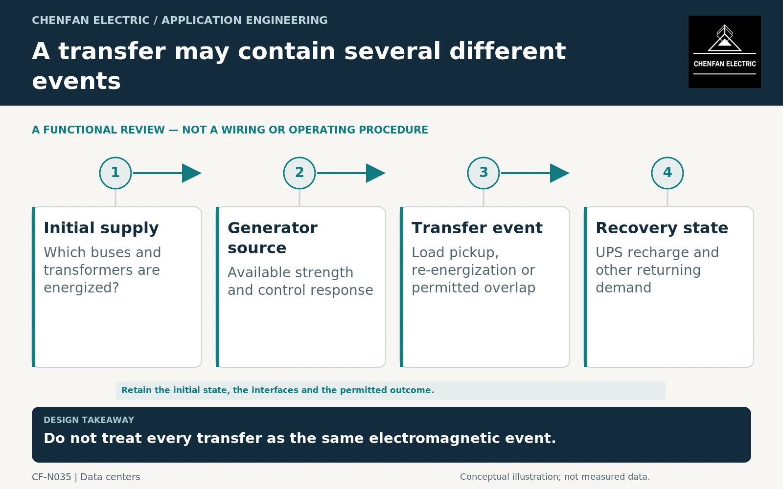
A data-center generator transfer should distinguish transformer re-energization from load pickup onto an already energized transformer. The initial electrical state determines which phenomena need assessment. Generator strength, controls, connected cables and returning uninterruptible power system (UPS) demand can all matter. A utility-supplied operating record does not automatically establish acceptable behavior on the standby source.
Identify what becomes de-energized
Map the source, transformer, bus and UPS states before, during and after the transfer. A dead transformer requires an excitation assessment when energized; an energized transformer receiving additional load presents a different event. Some architectures involve both at different stages.
Record any intended overlap or synchronization requirement as a project-controlled operating state. This article does not prescribe switching steps or authorize live-source paralleling.
Transformer application guidance addresses connections and operating conditions. The generator-transfer scheme must provide the actual sequence and source boundaries. [1]
Review excitation against the generator source
Transformer energization depends on nonlinear excitation, initial magnetic state, switching conditions and the connected network. A generator source can respond differently from a strong utility system, so the relevant source model and control behavior must be included.
CIGRE’s energization study-guide summary identifies voltage dips and temporary overvoltages as possible system consequences. It supports the need for a coordinated study, not a universal multiplier for generator or transformer sizing. [2]
Request suitable transformer excitation information and identify model limitations. A steady-state percentage impedance alone does not describe the complete energization response. Software workflows for varying closing conditions are useful only when the underlying models and initial conditions are appropriate. [3]
Include the loads that return after transfer
UPS rectifiers, battery recharge, cooling equipment and other facility loads may return on different schedules. Their combined demand can govern a later interval even if transformer energization itself is acceptable.
| Event | Data needed |
|---|---|
| Transformer energization | Excitation model, source state and connected network |
| UPS input restoration | Input limit, ramp behavior and recharge setting |
| Motor restart | Starting method and permitted sequence |
| Sustained generator operation | Coincident current and reactive demand |
| Return to utility | Approved topology and transition assumptions |
IEC 62040-3 concerns UPS performance and testing within its scope. It does not certify the complete generator-transformer-UPS interaction, which must be assessed using the installed configuration. [4]
Avoid using an average facility demand to represent all these events. Equally, do not add every theoretical maximum if controls make those conditions mutually exclusive; document the controls that enforce the restriction.
Define a staged acceptance plan
The design package should identify study cases, parameter owners and acceptance boundaries before integrated testing. Distinguish component test evidence from a demonstration of the complete transfer scheme. A transformer factory report does not verify generator control behavior, and a generator load-bank test does not automatically represent transformer energization.
Keep any restrictions visible: maximum connected load at transfer, recharge limitations, unavailable cooling cases or permitted source configurations. These conditions are part of the usable system duty.
The practical result is a state-by-state transfer record linked to the electrical models and implemented controls. That record prevents the vague instruction “check inrush on generator” from concealing a more complex sequence of excitation, load pickup and sustained post-outage demand.
Core procurement checkpoint: Keep energization acceptance distinct from generator-transfer proof
For generator transfers, agree what excitation information the transformer manufacturer will supply to the study team and under what conditions it applies. A bare-core loss test is not a complete test of the transformer-generator transfer sequence. In the core order, specify the geometry, material and agreed test state while assigning residual-flux assumptions, switching sequence and protection validation to the appropriate project parties.
For the core enquiry: Core design revision; requested excitation records; test configuration; model owner; transfer-study and commissioning responsibilities.