

The tap range of a photovoltaic (PV) transformer should follow the collector-system voltage study and the inverter’s permitted terminal-voltage range. Copying a familiar percentage range from another project can leave the inverter outside its operating window or create unnecessary design complexity. The useful result is a schedule showing which ratio positions serve the credible network conditions and how those positions are selected.
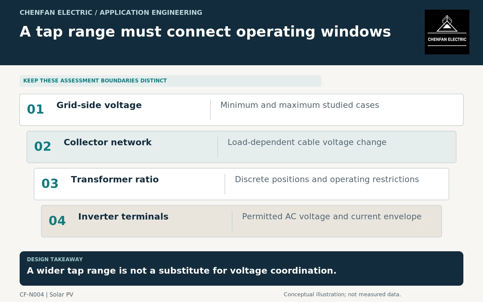
Study voltage at the inverter, not only at the substation
The inverter terminal voltage depends on the upstream voltage, transformer ratio and voltage changes across the transformer and collector cables. Active and reactive power both influence those changes. Their effects also depend on network impedance and the direction of power flow.
Separate the reference points in the study model. A voltage requirement at the point of interconnection is not automatically the same requirement at a low-voltage inverter terminal. State whether plant controls regulate a collector bus, an inverter terminal or another metering point.
Transformer application guidance includes voltage variation, rating and tap considerations; it does not select a project tap range without the network cases. [1] Use the inverter’s actual permitted voltage-current envelope, not a nominal alternating current (AC) voltage printed without its operating restrictions.
Build a case set that can expose conflicting needs
At minimum, compare high and low upstream voltage with the relevant export, reactive-power and low-output conditions. Cable charging and nighttime support may matter even when active export is small. Include future collector extensions only when they are part of the approved design basis.
| Study case | Potential constraint to check |
|---|---|
| High upstream voltage with export | Upper inverter-terminal voltage |
| Low upstream voltage with reactive support | Current limit and lower operating voltage |
| Little active output on long cables | Reactive behavior and voltage-control interaction |
| One collector section unavailable | Changed flows and remaining operating positions |
Do not combine unrelated extremes merely to produce an impossible worst case. Equally, do not omit an inconvenient but credible combination because the average production case is satisfactory. The operating-case register should identify which combinations are physically and contractually possible.
Separate ratio coverage from tap-changing capability
A transformer may provide several ratio positions without being designed to change them while energized. The specification must distinguish the physical tap range from the operating method and from the plant’s voltage-control strategy. Never assume an off-circuit device can perform an online regulating function.
Where an on-load tap changer is proposed, define its role relative to inverter reactive-power controls and any upstream voltage regulator. Control deadbands, priorities and time coordination belong to the system design. A larger number of positions does not, by itself, prevent conflicting regulators from responding to one another.
Also ask how tap position affects guaranteed ratings and the study impedance model. A single impedance value at a principal tap may be insufficient for the cases being evaluated. Insulation requirements and test levels require their own coordination; selecting a voltage ratio is not the same task as specifying dielectric withstand. [2]
Turn the study into a purchasing schedule
The final schedule should state winding nominal voltages, the ratio convention, each required tap position, the intended initial position and the permitted method of changing it. Attach the voltage cases and inverter operating limits that justify the range. Identify any position that is reserved for a contingency rather than continuous operation.
Require the supplier to confirm its ratio schedule against that document before manufacturing information is frozen. The site commissioning plan can then verify the installed position and compare measured terminal voltages with the approved operating assumptions, without treating commissioning as a redesign exercise.
The purchasing decision is complete when every required operating case has a defensible ratio position and a compatible control philosophy. “Standard taps supplied” is not evidence that this coordination has occurred.
Core procurement checkpoint: Tie the magnetic design to the selected tap scheme
A tap-range percentage alone is not a core specification. Ask the transformer designer to identify the voltage, frequency and effective turns used to establish the magnetic design for the relevant operating cases. Release the core drawing only after that review. Changing a tap schedule after cutting can require a design reassessment even when the external core dimensions appear unchanged.
For the core enquiry: Approved tap-related design basis; core drawing revision; material specification; loss and excitation acceptance conditions.