

A photovoltaic (PV) step-up transformer should be specified from the inverter-side alternating-current (AC) operating envelope, not by copying the solar array’s direct-current (DC) megawatts into a transformer rating. The decisive inputs are voltage, continuous current, simultaneous active and reactive power, and the conditions under which those quantities can occur. Array capacity remains useful for plant planning, but it does not describe every load imposed on the transformer.
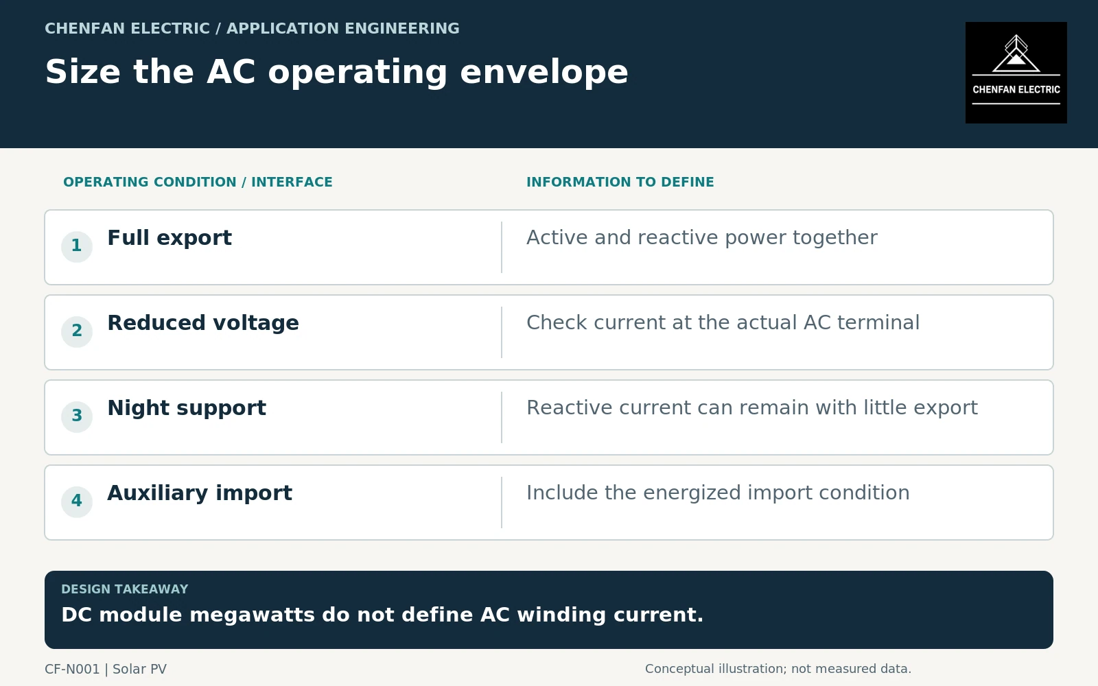
Put all ratings at the same electrical boundary
Start by identifying whether each quoted value belongs to the modules, inverter direct-current input, inverter alternating-current terminals, transformer terminals or point of interconnection. Losses and auxiliary consumption separate these boundaries. A plant-level export limit is not automatically a limit on an individual low-voltage winding.
For balanced, approximately sinusoidal three-phase operation, apparent power is S = √(P² + Q²), and line current is I = S/(√3 × VLL), using consistent units and root-mean-square line-to-line voltage. This relationship is an engineering calculation, not a substitute for a manufacturer’s current limit. Where distortion is material, obtain total root-mean-square current and its spectrum rather than relying only on fundamental-frequency P and Q.
An illustrative inverter block supplying 4.0 MW and 1.5 MVAr simultaneously carries about 4.27 MVA. At 0.8 kV line-to-line, the corresponding sinusoidal current is about 3.08 kA. These assumed values demonstrate the boundary issue; they are not a proposed transformer size.
Obtain the inverter’s actual capability envelope
A headline megawatt rating may apply only within particular voltage and temperature conditions. Ask whether the quoted current is continuous, temporary or subject to control-dependent restrictions. Identify the reactive-power priority setting: maintaining reactive output during a voltage reduction can change the active power available within the same current ceiling.
Do not assume that maximum P and maximum Q listed separately can occur together. Equally, do not assume that the inverter stops imposing transformer duty after sunset. Some products offer nighttime reactive-power operation and consume active power for their own assemblies during that mode. That is a product-specific capability, not a universal PV requirement. [1]
Record the firmware-dependent control modes and the guaranteed electrical limits, rather than copying a marketing capability plot without its notes. An unavailable or disabled mode should not silently become part of the continuous design basis.
Convert operating states into winding duties
Transformer application guidance addresses rating, connections, taps and operating conditions; the project still has to supply the actual cases. A loading guide can then support a thermal assessment within its own scope, rather than turning annual energy yield into a nameplate rating. [2] [3]
| Operating state | Information needed at the transformer |
|---|---|
| Maximum daytime export | Simultaneous P, Q, voltage and duration |
| Low-voltage support | Current limit, control priority and permissible duration |
| Nighttime operation | Reactive duty, auxiliary import and energized hours |
| Restricted cooling | Ambient conditions and available cooling equipment |
Use credible combinations. Maximum ambient, maximum reactive power and maximum export are not necessarily simultaneous, but the specification must explain when they are. Review each winding separately where several inverter groups share a transformer.
Issue an enquiry that can be checked
The enquiry should include the approved single-line diagram, inverter model and revision, AC terminal voltage range, continuous and temporary current limits, operating-state table and cooling assumptions. Add harmonic information, earthing arrangements and the collector-system study as separate inputs; they cannot be inferred from DC array capacity.
Define the acceptance boundary as well. A supplier should be able to identify which operating cases govern current, insulation and temperature assessment, and which remain conditional on missing converter data. Preserve the distinction between a core design, an assembled transformer and plant performance: selecting a core material alone cannot demonstrate that an inverter-transformer combination meets the complete operating envelope.
Core procurement checkpoint: From AC duty to a core drawing
Once the transformer designer has established the inverter operating envelope, convert it into a controlled core drawing rather than ordering a core by solar-array megawatts. The core enquiry should identify the selected geometry, electrical-steel specification and loss-test basis. A material certificate describes the supplied steel under stated test conditions; it does not establish the completed inverter transformer’s losses or thermal performance.
For the core enquiry: Drawing revision; limb and window dimensions; specified grade and thickness; agreed frequency, flux density and core test state.