

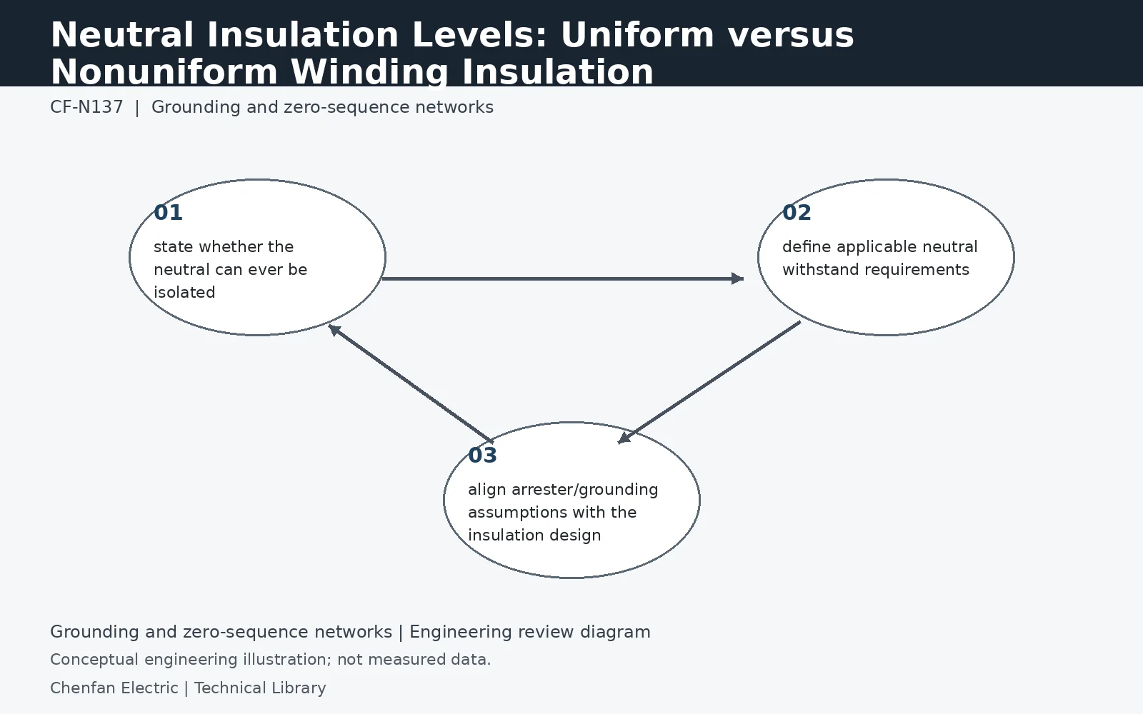
Neutral insulation may be uniform with the line end or deliberately reduced in a graded/nonuniform insulation design. That choice must match grounding and overvoltage assumptions. A neutral intended to remain effectively grounded can have different insulation requirements from a neutral that may be isolated or exposed to transferred surges. Procurement should therefore state neutral operating conditions and required dielectric withstand rather than assuming all terminals are equivalent.
Reduced neutral insulation is a system-dependent design
A nonuniformly insulated winding can assign a lower dielectric level at the neutral than at the line terminal. It is not a statement that the neutral experiences zero voltage under every disturbance. The design relies on defined grounding and overvoltage conditions. Identify the line-end and neutral-end withstand requirements separately, together with the applicable test configuration. A purchaser should not replace those fields with a single insulation number copied across every terminal.
Study a lost grounding path as a distinct condition
A disconnected neutral lead, unavailable grounding assembly or changed operating configuration can invalidate an assumption of effective grounding. Whether that condition is permitted, prevented or cleared must be decided at system level. The resulting neutral voltage and exposure time inform the insulation assessment. Do not treat a neutral disconnector as a harmless maintenance accessory when its state can change the electrical duty of a winding designed with reduced neutral insulation.
Coordinate the bushing, lead and surge protection
The winding neutral insulation is only one part of the interface. Neutral bushings, external leads, clearances and any arrester must also suit the specified service. An arrester's protective level must be considered together with its continuous-voltage and temporary-overvoltage capability; simply choosing the lowest protective level is not sufficient. The approved insulation schedule should show which assumptions are guaranteed by equipment design and which depend on station grounding and protection logic.
Technical reference framework
[1] IEC 60076-8:1997 — Application guide.
[2] IEC 60076-1:2011 — Power transformers, General.
[3] Post Glover NG112-06 — Neutral grounding resistors: Technical information.
[4] Post Glover GT210-10 — Neutral grounding resistors with transformer.