

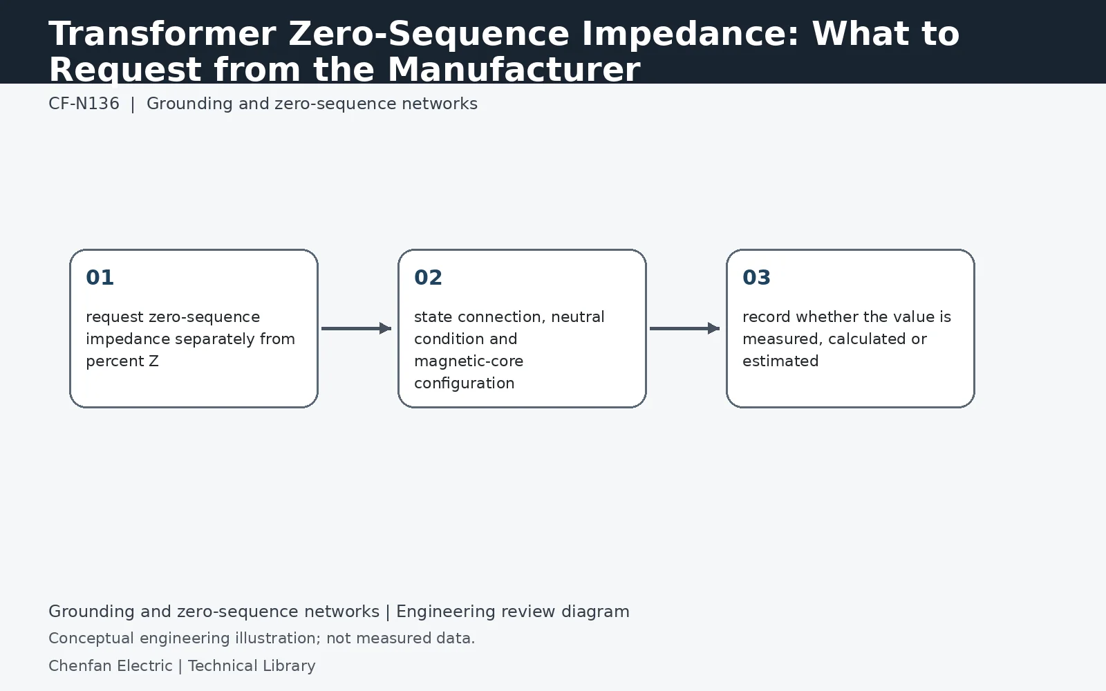
Zero-sequence impedance is not interchangeable with positive-sequence short-circuit impedance. Its value depends strongly on winding connections, neutral grounding and magnetic return path, including whether a three-limb or five-limb core or tank path participates. Request the manufacturer data in the form needed by the study, with test/calculation basis, tap position, frequency and relevant terminal conditions.
A three-limb core changes the magnetic return path
Balanced positive-sequence fluxes can sum to approximately zero within a three-limb core. Zero-sequence fluxes are in phase and require a different return path, potentially involving air, structural parts and the tank. A five-limb or shell-form design offers a different magnetic circuit. Winding connections, including a closed delta, can further change the terminal response. This is why a positive-sequence impedance copied from the nameplate is not a reliable substitute for the requested zero-sequence model.
Specify what is connected during the measurement
A useful data request identifies the energized winding, connections of the other windings, neutral treatment, tap position and test frequency. Ask whether the result is measured or calculated and whether resistance and reactance are available separately. Where excitation level affects the response, request the applicable range rather than one unexplained number. If the supplier supplies ohms, identify the referred winding; if it supplies per-unit values, record the MVA and voltage bases.
Avoid counting the grounding impedance twice
The model handoff must state whether the reported terminal impedance includes the external neutral resistor or reactor. If it does, adding that grounding element again in the network model produces an incorrect earth-fault result. If it does not, the external element still needs to be represented on the correct basis. Retain a simple connection sketch alongside the data so that the protection engineer can distinguish transformer zero-sequence behavior from the installed system's complete grounding path.
Technical reference framework
[1] IEC 60076-8:1997 — Application guide.
[2] IEC 60076-1:2011 — Power transformers, General.
[3] Post Glover GT110-08 — Zig-zag grounding transformers.