

Electromagnetic design handover should convert the transformer’s operating requirements into a controlled magnetic definition that the core manufacturer can implement and verify. A core outline alone is insufficient, while an unfiltered system-model archive may be unusable. The handover must preserve the assumptions that affect the supplied core without transferring undefined system responsibility to its manufacturer.
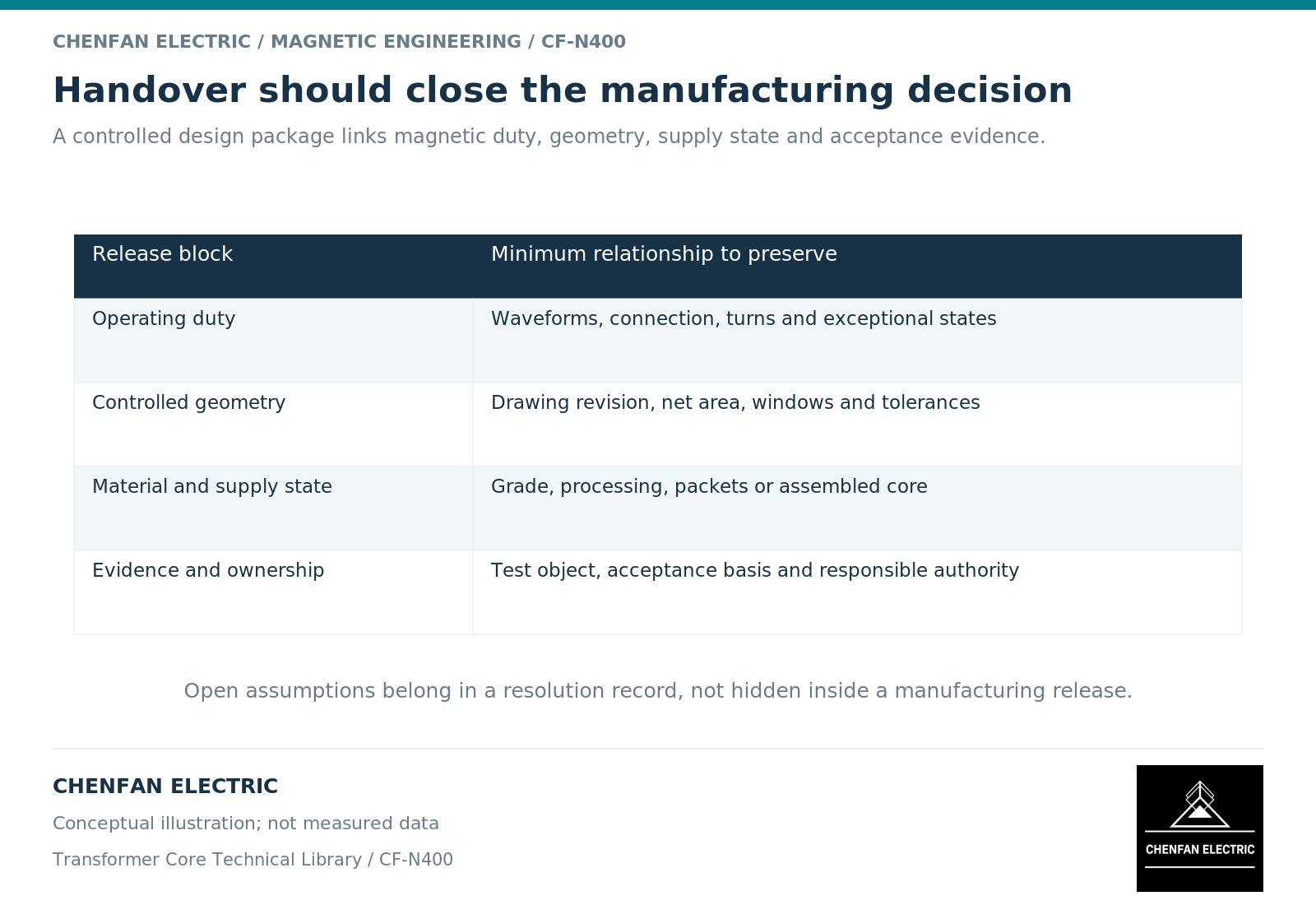
Freeze the magnetic definition before translating it into parts
Identify the topology, magnetic branches, net areas, path geometry and winding-to-core relationship relevant to the design. Multi-limb magnetic models demonstrate why geometry and winding coupling must be represented consistently. [1]
State the induced-voltage basis, active turns, frequency, waveform and operating envelope used to establish the required flux excursion. Faraday’s law provides the connection between these electrical inputs and the magnetic duty. [2] Label line versus phase voltage and root-mean-square versus peak quantities wherever they appear.
The core manufacturer’s section schedule and cutting or stacking definition should implement this magnetic design. They are not substitutes for it. A section change that preserves an outer diameter can still alter net area, joint geometry or branch behavior.
Where the original equipment manufacturer retains a proprietary system model, a controlled interface specification can provide the necessary magnetic requirements without exposing unrelated design data. The important condition is that the supplied requirements remain sufficient, unambiguous and traceable.
Separate design inputs, manufacturing requirements and evidence
The handover should distinguish three classes of information. Design inputs establish the required duty. Manufacturing requirements define the supplied object. Verification requirements define which evidence is needed and at what assembly level.
| Handover item | Required definition |
|---|---|
| Magnetic operating envelope | Voltage integral, frequency, turns and relevant exceptional cases |
| Core geometry | Topology, net areas, section schedule, joints and controlled revision |
| Material basis | Identified grade or approved equivalence criteria and processing state |
| Mechanical interfaces | Windows, reference datums, supports and installation boundaries |
| Electrical interfaces | Intended grounding and insulation features within supply scope |
| Verification scope | Material, parts, assembled core or complete-transformer object |
| Change authority | Who may approve each class of deviation |
A material certificate supports the identified material. A dimensional report supports inspected geometry. An assembled-core magnetic result supports that test object under its stated conditions. None should be renamed to imply a complete-transformer test.
The handover should also state what is excluded. Winding manufacture, complete-transformer dielectric performance, system protection and converter control are not automatically core-supply responsibilities.
Make deviations reviewable rather than implicit
A proposed substitution should identify the exact requirement affected and the reason for the change. Examples include another section combination, a revised joint detail, an alternative material or a different delivered assembly state. “Equivalent core” is not a complete deviation request.
The designer should evaluate whether the change affects excitation, losses, leakage-related interfaces, mechanical fit or the original verification basis. The manufacturer should state its manufacturing consequence and available evidence. Record the decision in the controlling documents before treating the change as released.
This division also applies when a winding revision leaves the core unchanged. The manufacturer may continue using the same core drawing, while the original equipment manufacturer updates its active-part field or thermal review. Keeping the core part number does not approve the wider change automatically.
Retain assumptions with the corresponding result
Every calculated or tested quantity should identify its object, conditions, units and provenance. A model output should not be presented as a factory measurement. A sample result should not be presented as an assembly guarantee. A provisional assumption should remain visible until replaced by an approved input.
For an illustrative handover discrepancy, one team may calculate flux density using net steel area while another interprets the listed area as gross stack area. Both can reproduce their own arithmetic and still disagree. Resolving the area definition is more useful than exchanging revised numbers without changing the underlying record.
The same principle applies to voltage reference, tap turns, winding connection and waveform. A concise assumption table can prevent repeated misunderstandings when several parties exchange drawings and reports over time.
Close the release with a reproducible package
The final handover should contain the approved magnetic specification, manufacturing drawing set, material definition, interface responsibilities, agreed verification plan and resolved deviation record. Each should carry a compatible revision and identify the supplied state.
The receiving team should be able to determine which document governs a dimension, which establishes a magnetic requirement and which proves an actual inspection or test. Missing information should be assigned to a named role and a specific decision rather than hidden in a general approval note.
For Chenfan Electric core supply, this creates a practical boundary: the transformer designer defines and approves the system-derived magnetic duty; the core manufacturer implements the agreed core and supplies the contracted evidence. A complete handover connects those responsibilities without confusing them, making subsequent manufacture, comparison and change control substantially more reliable.
References
[1] Manitoba Hydro International / PSCAD. The UMEC Approach.
[2] Lloyd Dixon / Texas Instruments. Magnetics Design 1 – Introduction and Basic Magnetics.