

Changing frequency can change flux excursion, loss mechanisms and the validity of a magnetic model at the same time. A simple scaling rule is useful only when the quantities held constant are stated. Constant voltage, constant volts per hertz and constant flux waveform are different comparisons.
State what remains unchanged
For sinusoidal induced voltage with fixed turns and area, peak flux density is proportional to voltage divided by frequency. [1] At constant voltage, increasing frequency reduces that ideal flux amplitude. At constant volts per hertz, the amplitude remains unchanged while the rate of traversal changes.
A core-loss comparison at fixed peak density therefore answers a different question from a transformer operated at fixed terminal voltage. Do not combine curves from those two conditions into one claimed frequency trend.
Waveform shape also matters. Maintaining the same root-mean-square voltage while changing pulse width or modulation does not necessarily preserve the same flux excursion or local reversal history.
Loss contributions do not share one universal exponent
Hysteretic and induced-current effects respond differently to excitation rate and waveform. A fitted power law may summarize a limited dataset, but its exponents are not universal constants for every material, temperature and frequency range.
If a model is calibrated over one band, show the supported band and the distance to the intended operating case. Extrapolating a smooth curve is numerically easy; demonstrating that the same physical approximation remains valid is a separate task.
Effective frequency-domain material descriptions are designed for particular representations of periodic behavior. They should not be assumed to reproduce arbitrary transient histories or every harmonic component. [2]
Check geometry and electromagnetic penetration
At different frequencies, conducting regions can exhibit different field penetration and loss distributions. A homogenized lamination model or a coarse structural mesh may require reassessment if the relevant spatial scales change.
Winding current distribution can also change, so a total-transformer loss trend cannot be assigned to the core alone. Keep the core material, winding and structural contributions separately identified in the comparison.
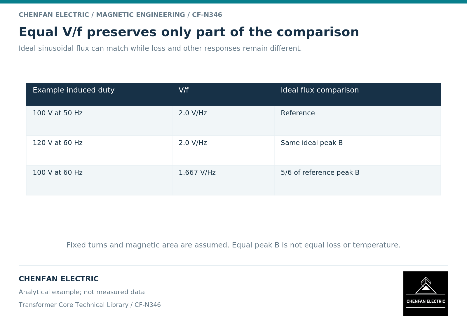
An illustrative magnetic comparison makes the operating distinction clear. A winding at 100 volts and 50 hertz has the same ideal sinusoidal flux amplitude as the same winding at 120 volts and 60 hertz. At 100 volts and 60 hertz, its amplitude is five-sixths of the first value. None of these ratios, by itself, gives the corresponding total loss ratio.
Use a frequency-validity matrix
| Model input or assumption | Question after frequency changes |
|---|---|
| Voltage and turns | Is the flux excursion still the intended one? |
| Material loss data | Does the dataset cover the new frequency and waveform? |
| Hysteresis representation | Is rate dependence included appropriately? |
| Conducting geometry | Is field penetration and current distribution resolved? |
| Thermal boundary | Are the changed losses evaluated under the correct cooling duty? |
The matrix should be completed before using a model to claim a frequency extension for an existing design. A successful solver run is not evidence that the underlying assumptions remain valid.
For technical procurement, specify the complete voltage-frequency-waveform envelope and the required performance quantities. The core supplier can then work against a defined magnetic design rather than a nominal frequency label. The final capability statement should remain within the range supported by data and validation, with extrapolation identified instead of hidden inside a scaling coefficient.
References
[1] Lloyd Dixon / Texas Instruments. Magnetics Design 1 – Introduction and Basic Magnetics.
[2] Nirmal Paudel / COMSOL. Model Magnetic Materials in the Frequency Domain with an App (2016).