

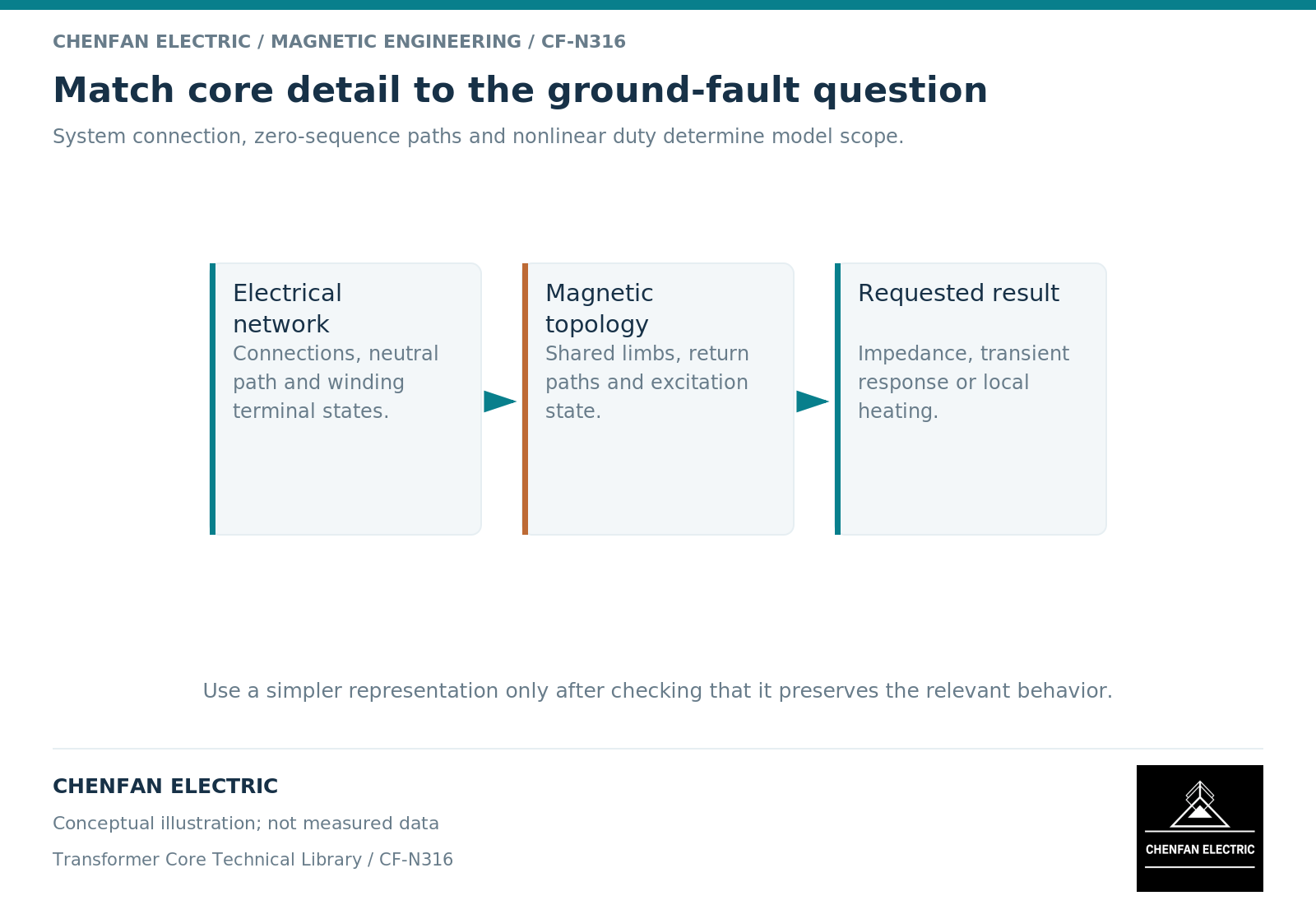
Magnetic detail is needed in a ground-fault study when the decision depends on nonlinear excitation, unusual return paths or transient waveforms that a fixed sequence impedance cannot represent. It is not automatically necessary for every calculation of fault current. Choose the model from the question, then demonstrate that its simplifications do not change the decision.
Start with the required output
A conventional network study may need terminal currents and voltages for a defined set of system conditions. If a connection-specific sequence equivalent represents the transformer adequately over those conditions, a detailed field model can add complexity without improving the relevant result.
A different study may investigate saturation, temporary overvoltage, waveform asymmetry or the effect of a changing magnetic return. Those questions can require nonlinear branches and magnetic coupling. Geometrical equivalent-circuit models provide one way to retain core topology without solving a full three-dimensional field problem. [1]
The choice is therefore not “simple versus accurate.” It is “which omitted effects matter to this observable?” A detailed model with unidentified parameters can be less defensible than a simpler model validated for a narrow purpose.
Separate the electrical connection from the core topology
The electrical model needs winding connections, neutral treatment, other winding terminal states and the relevant impedances. The magnetic model needs the core form, return paths, nonlinear characteristics and initial state when transients matter.
These are complementary inputs. A five-limb core does not override a disconnected neutral. A grounded neutral does not establish the reluctance of a three-limb external return. A closed tertiary winding can change the terminal response without changing the physical number of limbs.
The nonlinear branch must also be connected consistently within the equivalent circuit. Its location relative to leakage impedance matters when saturation drives substantial current. [2] Merely adding a generic saturation curve to an existing network model is not a complete upgrade.
Use a staged model-selection test
| Decision stage | Question to resolve |
|---|---|
| Define the case | Which fault, connection, duration and pre-fault state matter? |
| Screen the approximation | Can a fixed sequence equivalent cover the expected range? |
| Add nonlinear detail | Which saturation or topology effect changes the output? |
| Check evidence | Which measurement or independent calculation constrains that effect? |
| Bound the conclusion | Which operating cases remain outside the model’s support? |
This staged approach is particularly useful when transformer data are incomplete. It identifies the missing information with the greatest effect on the study instead of requesting every manufacturing dimension indiscriminately.
For example, uncertainty in an external magnetic return may matter little to one terminal-current result but strongly affect an inferred structural-loss result. The same model can be adequate for the first and inadequate for the second. Its acceptance should state that distinction.
Deliver assumptions with the result
The study handover should include the transformer model type, parameter origins, connection diagram, topology description and sensitivity cases. Separate measured quantities from fitted parameters and unverified defaults. Do not allow a software library default to become an unnamed product characteristic.
Where thermal consequences are relevant, provide the excitation history and loss assumptions to the thermal assessment. A ground-fault current calculation alone does not demonstrate acceptable local core, clamp or tank temperature.
For technical procurement, the actionable request is specific: confirm the model input or operating envelope that controls the study. Asking a core supplier to approve the complete ground-fault behavior from a lamination drawing crosses the evidence boundary. The original equipment manufacturer and system-study engineer must retain responsibility for the complete transformer and its network connection.
References
[1] Manitoba Hydro International / PSCAD. The UMEC Approach.
[2] Manitoba Hydro International / PSCAD. The Classical Approach.