

A five-limb core provides outer iron return paths that a three-limb core does not have. Its zero-sequence response therefore needs its own magnetic representation. Copying a three-limb model and changing only the mass or no-load loss leaves the central topological difference unresolved.
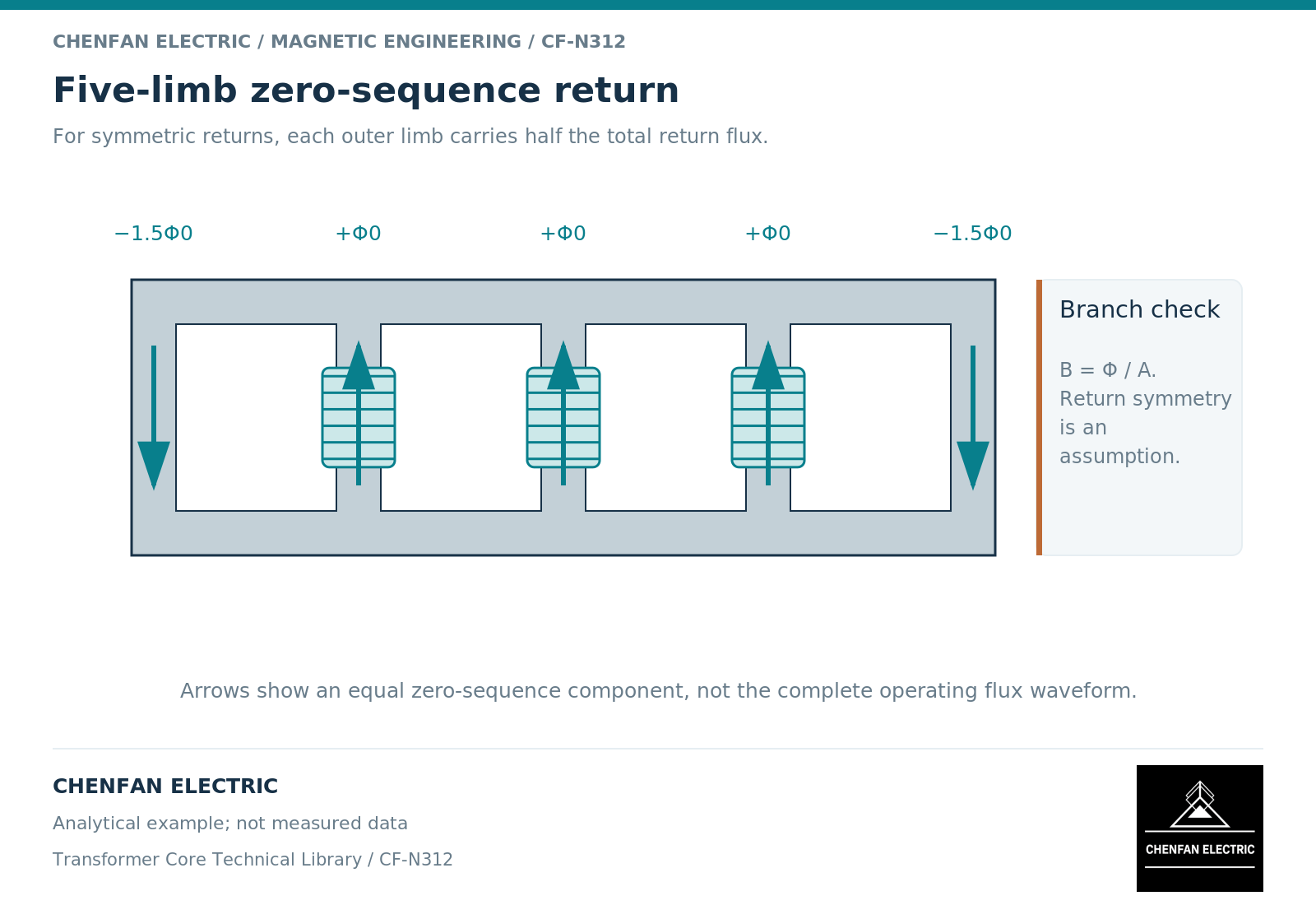
The extra limbs carry a different combination of flux
Three in-phase wound-limb components do not cancel at a yoke. The two outer limbs can return their sum through steel. Under ideal left-right symmetry, each outer limb carries half of that combined return component. Real branch areas, path lengths and nonlinear material response determine how closely this idealization applies.
This is not a claim that an outer limb always carries half the flux of one wound limb. Its duty depends on the instantaneous combination of all phase components. Balanced operation, zero-sequence excitation and mixed unbalanced operation produce different branch duties. A geometrical model can represent these coupled paths rather than assigning independent phase inductances. [1]
The outer-limb cross-section must consequently be interpreted with its flux duty. Comparing its width with a wound limb’s width, without tracing the flux combination, is not a saturation assessment.
An iron return is nonlinear, not unlimited
At relatively low excitation, an iron return can have a very different reluctance from an external air-and-structure return. As local flux density rises, the incremental permeability changes. The division of flux among available paths can then change as well.
An illustrative arithmetic check makes the area issue visible. Suppose three equal zero-sequence components are each 0.002 weber. Their sum is 0.006 weber. If two identical outer branches share it equally, each carries 0.003 weber. With a net area of 0.002 square metre, that component alone corresponds to 1.5 tesla. These invented values demonstrate continuity and area accounting; they do not establish an allowable operating point.
The actual peak density could include other components. Add signed, time-aligned branch waveforms before identifying the maximum. Adding unrelated peak magnitudes may be unnecessarily conservative, while checking the zero-sequence component alone may miss a critical instant.
Preserve the winding circuit around the core
The magnetic return path does not independently determine the terminal zero-sequence impedance. Winding connections, neutral impedance, closed tertiary circuits and leakage coupling establish which ampere-turns reach the magnetic network.
This is especially important when comparing two models calibrated from different tests. A terminal measurement with a compensating winding closed is not interchangeable with a measurement made without that response. A fitted nonlinear branch may appear satisfactory at one test connection yet fail when the operating connection changes.
A saturation characteristic also needs a stated reference winding and flux-linkage basis. Classical circuit models show how branch placement and leakage drops affect nonlinear behavior. [2] A model file without those definitions is not fully specified simply because its curve looks smooth.
Request a five-limb validation matrix
For a design review, organize the evidence by excitation rather than by drawing count. Include a balanced case, the relevant zero-sequence case and any mixed condition that controls the project. For each, identify terminal connections, applied waveform, return-limb response and the comparison quantity used for validation.
The matrix should distinguish material data, geometric calculations, assembled-transformer measurements and extrapolated operating cases. Where outer-limb saturation has not been checked, mark that case outside the demonstrated range instead of extending a low-level inductance silently.
Five-limb construction is therefore a reason to model the return correctly, not a standalone statement of grounding suitability or fault capability. The accepted conclusion must belong to the complete electrical and magnetic configuration that was actually reviewed.
References
[1] Manitoba Hydro International / PSCAD. The UMEC Approach.
[2] Manitoba Hydro International / PSCAD. The Classical Approach.