

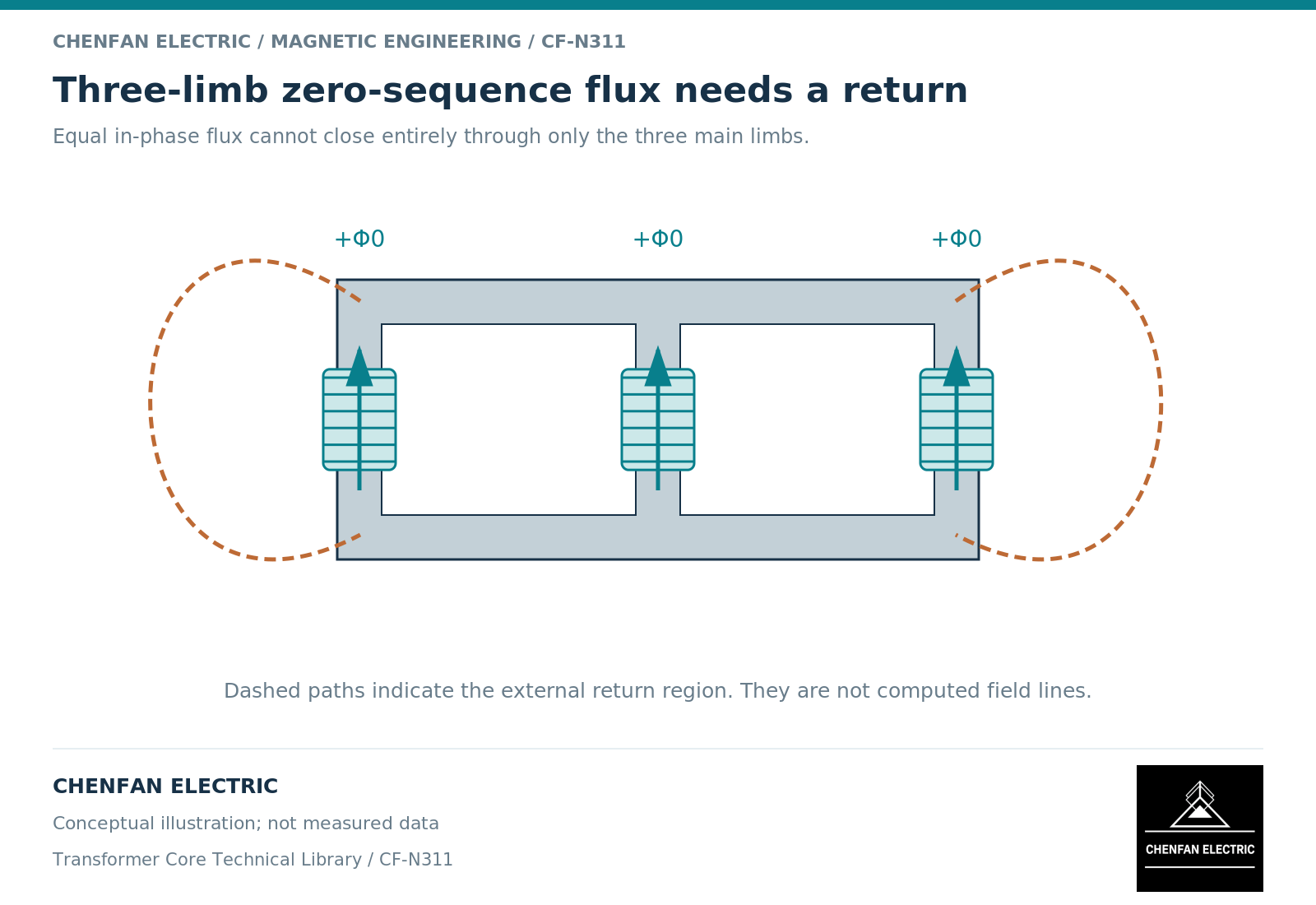
Zero-sequence flux in a three-limb core cannot complete its entire return through the other two wound limbs. Its three phase components point in the same instantaneous direction, so their sum requires a return outside the three-limb iron circuit. Air, insulating fluid and nearby metallic structures become part of that magnetic boundary. This is a topology statement, not a prediction of terminal fault current.
Add the phase components before drawing a return arrow
For signed limb fluxes Phi_a, Phi_b and Phi_c, the zero-sequence component is Phi_0 = (Phi_a + Phi_b + Phi_c)/3. Balanced sinusoidal positive-sequence components sum to zero. Equal, in-phase components instead give a total of 3Phi_0 at the yoke boundary. A diagram that sends all three downward and shows no return violates magnetic continuity.
The missing return is not an optional modeling detail when that component is important. A geometrical magnetic model represents shared branches and their reluctances, whereas three independent magnetizing branches do not automatically reproduce the same coupling. PSCAD’s unified magnetic equivalent circuit documentation explains this distinction. [1]
A useful sketch therefore shows two things: the three wound limbs and a separate external return region. The external region should not be drawn as a precise tank-wall path unless the geometry and field calculation support that choice.
Distinguish flux return from current return
A neutral conductor is an electrical path. A tank wall is potentially part of a magnetic and conducting structural region. Neither replaces the other in the equivalent circuit.
Whether appreciable zero-sequence magnetic excitation develops depends on winding connections, neutral treatment and the opposing ampere-turns available from other windings. A closed delta can provide a circulating-current response. An isolated neutral can constrain terminal currents. These electrical conditions must be resolved before interpreting the core’s magnetic response.
Consequently, the magnetizing zero-sequence branch is not necessarily the impedance measured at a chosen set of transformer terminals. Leakage impedances and other winding circuits may dominate that measurement. Ask which winding is excited, which terminals are connected together and what state every other winding has; do not accept an unlabeled value called simply “zero-sequence impedance.”
Use different models for different questions
For a network calculation, an equivalent external reluctance may adequately represent the relevant terminal behavior over an agreed range. For local tank heating, that same branch has no spatial information about induced current density or cooling. Matching one measured impedance does not validate a hot-spot prediction.
| Study question | Minimum boundary to identify |
|---|---|
| Terminal zero-sequence response | Winding connections and excitation level |
| Nonlinear magnetic response | Core topology and external return representation |
| Tank loss distribution | Structural geometry, conductivity and magnetic properties |
| Temperature rise | Loss distribution, duration and cooling conditions |
A saturation model also needs a consistent location for its nonlinear branch. Moving that branch across leakage impedance can change transient results; the classical-model documentation illustrates why the circuit arrangement matters. [2]
Make the external return explicit in the handover
The practical deliverable is a topology note attached to the model, not a universal numerical allowance. Identify the three-limb construction, the wound-limb and yoke branches, the representation of the external region and the operating cases used to check it. State whether structural losses are calculated, fitted into a lumped parameter or omitted.
For a core supplied separately from the transformer, the tank and active-part arrangement remain outside the bare-core geometry. A supplier can confirm that geometry without thereby validating the completed transformer’s zero-sequence heating. Keeping this boundary visible prevents a sound core drawing from being used as evidence for a different, untested system claim.
References
[1] Manitoba Hydro International / PSCAD. The UMEC Approach.
[2] Manitoba Hydro International / PSCAD. The Classical Approach.