

A rectangular core window can suit a racetrack winding, but window width and height alone do not establish compatibility. The curved winding ends, insulation build and end clearances must fit the complete active part. Compare magnetic path length and winding mean turn length separately; shortening one can lengthen the other.
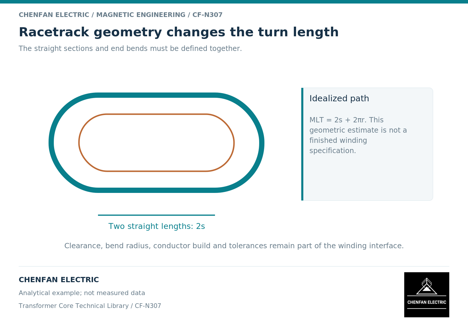
Follow the conductor around the ends
A racetrack winding combines straight portions with curved ends. Its mean turn length depends on both the straight length and the bend geometry. A rectangular window that accommodates the straight portion may still leave insufficient space for the end insulation, lead exits or cooling arrangement.
For a simple geometric racetrack with two straight sections of length s and two semicircular ends of mean radius r, the perimeter is 2s + 2pi r. This is a geometric relationship, not a complete winding design. The actual mean conductor path depends on the winding layer, radial build and conductor arrangement.
The magnetic path follows a different route through limbs and yokes. Changing the window proportions changes those path lengths and can alter core mass and excitation. A winding-perimeter calculation cannot substitute for the magnetic-circuit calculation. [1] [2]
A controlled geometry comparison
Take an illustrative racetrack mean path with s = 0.40 metre and r = 0.10 metre. Its perimeter is approximately 1.428 metre. If the straight section increases to 0.45 metre while the mean radius remains unchanged, the perimeter becomes approximately 1.528 metre, an increase of 0.100 metre per turn.
That difference is meaningful only if the compared paths represent the same winding layer and the same insulation definition. It does not directly predict total copper mass because turn count, conductor area, leads and parallel arrangements remain separate inputs. It also does not establish winding resistance without conductor material and temperature.
Conversely, narrowing the mean end radius may shorten the path but create a conductor-forming or insulation problem. The design should not treat bend geometry as an unlimited optimization variable. The original equipment manufacturer’s winding rules govern the admissible geometry.
Allocate the window before optimizing it
Use a cross-sectional allocation rather than a single fill percentage. Identify the core-to-winding insulation, each winding build, interwinding separation, cooling channels and the space required by supports. Then check the winding ends in the longitudinal view. A two-dimensional window fill can look satisfactory while the end region remains unresolved.
The allocation should distinguish nominal dimensions from minimum available space after tolerance accumulation. This is not a dimensional acceptance checklist: it is the design budget that makes later dimensional acceptance meaningful. A core manufacturer needs the released interface, not responsibility for inventing the winding clearance scheme.
Three particularly useful design questions are whether the end turns approach the yoke or clamps, whether the cooling route remains open around the end region, and whether the leads can leave the winding without changing the intended field environment. Each question links geometry to a different engineering boundary.
Compare complete candidates
Record magnetic and winding consequences side by side.
| Candidate change | Magnetic question | Winding question |
|---|---|---|
| Taller window | How does limb path length change? | Does straight conductor length increase? |
| Wider window | How do yoke length and flux paths change? | What happens to radial allocation and end geometry? |
| Different end radius | Is the core interface still compatible? | Are conductor forming and insulation provisions maintained? |
| Different support position | Does nearby steel intercept stray flux? | Is the winding mechanically supported as intended? |
A field model may be needed where the end arrangement or nearby conductive structure controls leakage loss. A planar model should not be presented as evidence for end-region behavior that it does not represent. [2]
The useful output is a matched core-window and winding-envelope definition, with the comparison constraints made explicit. The best rectangle is not necessarily the one with the smallest area or the highest apparent fill; it is the one that supports the required magnetic, electrical, thermal and mechanical design without hidden assumptions.
References
[1] Lloyd Dixon / Texas Instruments. Magnetics Design 4 – Power Transformer Design.
[2] David Meeker. Finite Element Method Magnetics User Manual.