

A stepped core section is an approximation to a circular winding interface, not a solid circle of magnetic steel. Compare the net magnetic area and the winding envelope separately. A section that appears to fill a circle efficiently may still require different insulation, support and cooling provisions from another section with the same nominal diameter.
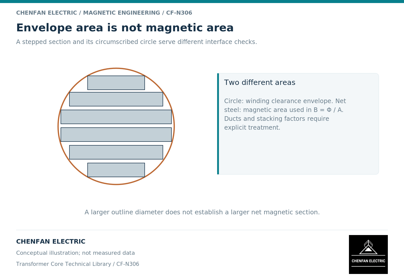
There are two different areas in the drawing
The magnetic calculation uses the net steel area normal to the principal flux. The winding designer works with an envelope that includes the core’s physical outline and the required insulation and assembly space. The circle surrounding the steps is therefore not automatically the area to insert into a flux-density calculation.
For a section assembled from packets of different widths, widths multiplied by gross packet builds give a gross stack area; the applicable stacking factor then gives net steel area. If the packet schedule already states net steel area, do not apply that factor again. Open cooling passages and deliberately nonmagnetic spaces must be treated consistently. The relationship B = Phi/A then uses the area definition associated with the magnetic model, not the area of the surrounding clearance circle. [1]
This distinction also prevents a misleading comparison between two drawings labeled with the same core diameter. Equal enclosing diameter does not imply equal net area, and equal net area does not imply equal winding perimeter.
More steps do not settle the active-part design
Increasing the number of steps can make the outline closer to a circle, but the value of that change depends on the winding construction. The designer must consider how the winding is supported, where insulation bridges between steps, whether cooling routes remain continuous and how the assembly is located relative to the core.
The winding’s mean turn length affects conductor quantity and resistance. However, the relevant path lies within the winding, not on the bare steel outline. Insulation thickness, radial build and conductor arrangement all separate those paths. A reduction in the core’s empty corner area cannot be converted directly into the same percentage reduction in copper loss.
Window allocation and winding losses are coupled to the core selection. Transformer-design guidance makes this coupling explicit, although numerical rules developed for small switch-mode transformers should not be transferred to utility-frequency equipment. [2]
An illustrative area check
Consider two hypothetical sections enclosed by the same 300 millimetre diameter circle. The enclosing area is pi multiplied by 0.300 squared divided by four, or approximately 0.07069 square metre. Suppose their independently calculated net magnetic areas are 0.0610 and 0.0640 square metre.
At a peak flux of 0.100 weber, their average peak flux densities would be approximately 1.639 and 1.563 tesla respectively. Substituting the full circle area would instead give 1.415 tesla and would understate both values. These figures illustrate the consequence of confusing an envelope with magnetic area; they are not dimensions or operating recommendations for a Chenfan product.
The comparison still says nothing about which winding is easier to manufacture or cool. Those questions require the actual winding interface. The calculation is deliberately limited to one magnetic-area error.
Release the interface as a matched definition
A useful design handover contains a section schedule and a winding-interface drawing that refer to the same revision. The section schedule identifies packet widths, thickness build and the net area basis. The interface drawing identifies the enclosing profile, support surfaces, insulation envelope and any orientation that must be preserved.
| Quantity | Do not substitute |
|---|---|
| Net magnetic area | Area of the enclosing circle |
| Core physical envelope | Bare conductor inner diameter |
| Winding mean turn length | Circumference of the bare core |
| Cooling passage area | Additional magnetic steel area |
Review a proposed change against both definitions. A change that preserves net area may alter the support geometry. A change that preserves diameter may alter flux density. Neither can be accepted solely because one headline dimension remains unchanged.
The appropriate number of steps is therefore a co-design result. It should serve the magnetic area, winding construction and assembly interfaces together, rather than become a standalone manufacturing feature used to claim better transformer performance.
References
[1] Lloyd Dixon / Texas Instruments. Magnetics Design 1 – Introduction and Basic Magnetics.
[2] Lloyd Dixon / Texas Instruments. Magnetics Design 4 – Power Transformer Design.