

Yoke cross-section should be selected from the flux carried by each yoke segment, not from a desire to make the core look geometrically symmetric. The correct area depends on topology, phase relationships, branch sharing and the operating cases included in the design. An equal-width outline can conceal unequal magnetic duties.
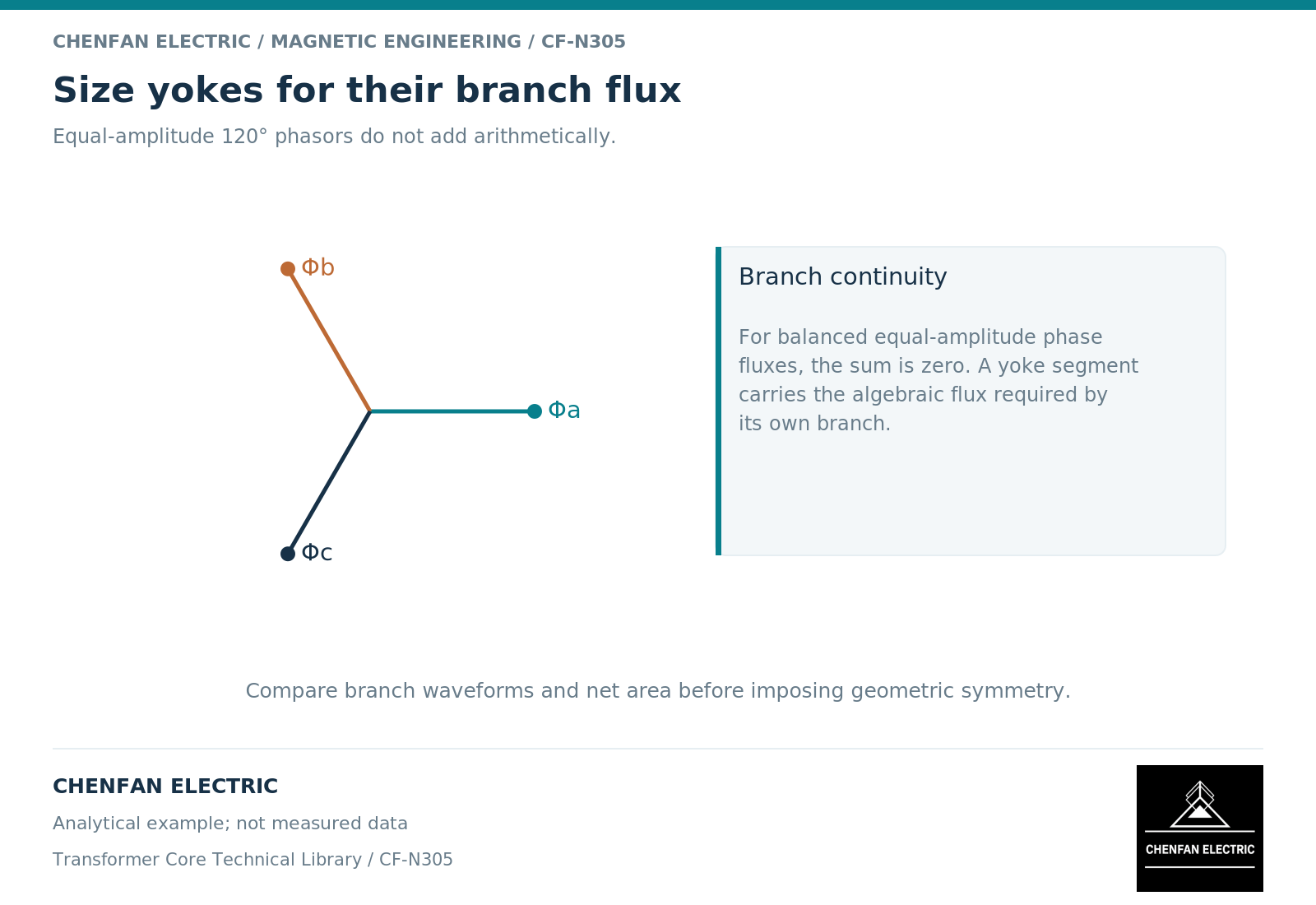
Divide the yoke into meaningful segments
A yoke is often drawn as one continuous horizontal member, but its magnetic loading should be considered between junctions. In a three-limb core, the segment between two adjacent limbs does not automatically carry the arithmetic sum of their peak flux magnitudes. The phase relationships and signed instantaneous fluxes determine what passes through that segment.
In a five-limb or shell-form arrangement, additional return branches create further junctions. Each junction requires flux continuity, and each segment inherits the flux needed to connect those branches. A magnetic network represents the yoke and limb reluctances separately because their lengths, areas and magnetic states need not be identical. [1]
For a drawing review, give the segments names before calculating them. This makes it possible to connect a field-model result, a cross-sectional schedule and a proposed dimensional change without relying on ambiguous phrases such as “the yoke flux.”
Apply continuity before dividing by area
For a selected segment, average density follows B = Phi/A. The area calculation is not the first step; the branch flux calculation is. Adding peak values from different phases as though they occurred simultaneously overstates some cases. Assuming cancellation without preserving phase information can understate others.
As an illustrative balanced case, let two limb fluxes be equal-amplitude sinusoids separated by 120 electrical degrees. Their sum is another sinusoid with the same amplitude as either one, not twice that amplitude. Which signed combination belongs in a particular yoke segment depends on the chosen directions and topology. This phasor result is a check on the network interpretation, not a complete yoke design.
Now add an in-phase component to all three limbs. The balanced cancellation argument no longer disposes of that component. Its return must be traced through the available branches, which may change the critical yoke section.
Examine local geometry without inventing a hot spot
The net cross-section can vary near junctions, openings or transitions. Flux also changes direction in these regions, and grain-oriented steel is not magnetically identical in every direction. Consequently, an average section density is a screening quantity, not proof that the local field is uniform. Material direction and the constitutive law matter in a detailed model. [2]
A field study should answer a defined question: for example, whether a proposed opening materially concentrates flux in the remaining steel. It should retain the actual opening geometry, material axes and relevant excitation. A colorful plot without a mesh check or a stated operating point cannot establish an acceptable local maximum.
Do not transfer a numerical limit from an unrelated specimen curve or a different steel-processing condition. The design authority must connect the chosen material evidence to the supplied core and its operating envelope.
A segment-by-segment release record
The following compact schedule is more useful than a single yoke-to-limb area ratio.
| Record field | Required content |
|---|---|
| Segment identity | Junction-to-junction location on the controlled drawing |
| Flux basis | Signed waveform or peak result for each governing case |
| Magnetic area | Net steel area and exclusions used in the calculation |
| Material treatment | Rolling direction and nonlinear data where relevant |
| Review result | Limiting case, unresolved assumptions and approved revision |
Include any height constraint in the same record. Reducing yoke height while increasing width may preserve area but alter magnetic path length, joint geometry and the active-part envelope. Preserving area alone does not prove that the redesign is equivalent.
The final manufacturing schedule should reproduce the reviewed segment areas and interfaces. If a change affects those quantities, it belongs back in the electromagnetic change process. Yoke selection is a flux-distribution decision carried into geometry, not a symmetry rule applied to an outline.
References
[1] Manitoba Hydro International / PSCAD. The UMEC Approach.
[2] Cesare Tozzo / COMSOL. Modeling Ferromagnetic Materials in COMSOL Multiphysics.