

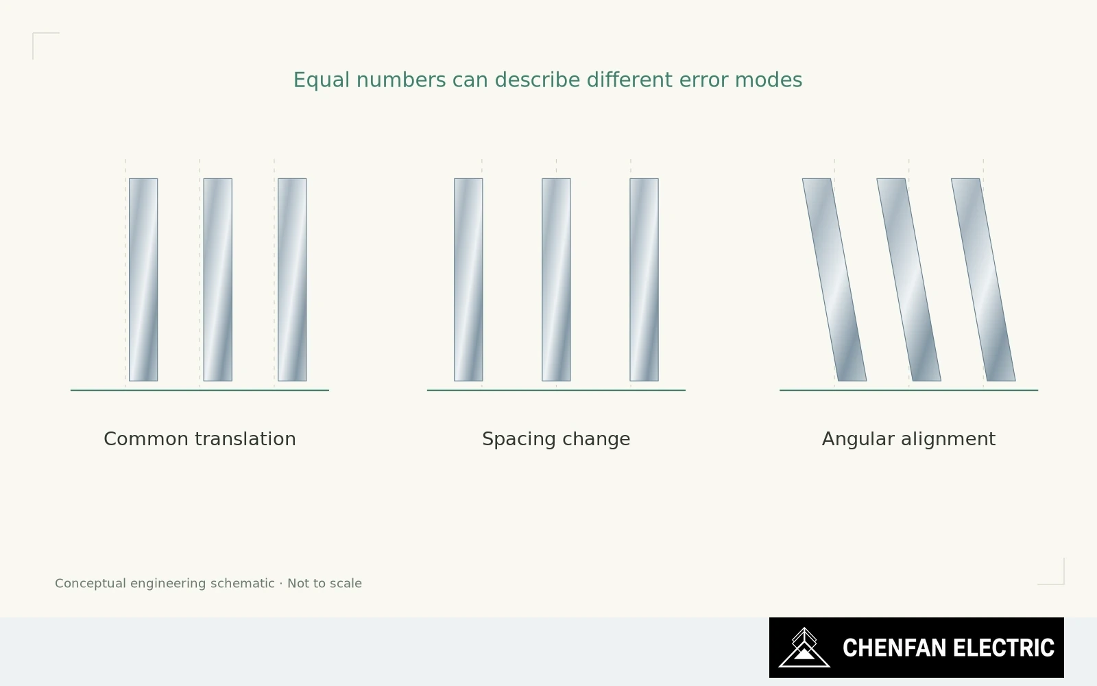
Two centre-distance deviations of the same magnitude can require completely different corrections.
One may be a common shift of the core relative to the frame. The other may change the spacing between limbs. Treating them as the same defect can send the adjustment to the wrong interface.
Define the datum and measurement height
Begin by identifying the datum and the relationship being measured. Is the requirement limb-to-limb spacing, position relative to the clamp structure, or alignment with the winding assembly? A centre-distance number without that reference leaves room for incompatible interpretations.
Measure at the locations that represent the functional geometry. A satisfactory spacing near one yoke does not prove that the limbs remain parallel over the winding height. Angular misalignment can produce a changing clearance along the coil’s insertion or final position.
The adjacent assemblies constrain the solution. Coils, spacers and clamps may each meet their own dimensions while leaving insufficient freedom to absorb the core deviation. An adjustment that improves one limb can worsen another interface if the overall geometry is not considered.
Distinguish translation, spacing and angular errors
This is why the first response should not be “move it until the coil fits.” Establish whether the apparent error comes from the core geometry, the measurement datum, the support state or the receiving assembly. Otherwise, a local fit correction can conceal the original cause and redistribute the problem.
Use a common coordinate system where practical. Record the actual limb positions as well as derived distances when those positions are needed to distinguish translation, spacing and angular errors. A single averaged distance can erase the pattern that identifies the mechanism.
The tolerance allocation should reflect these different modes. A frame-location allowance does not automatically authorize a change in magnetic-joint seating or limb spacing. The permissible adjustments need to be defined by the design.
Verify every connected interface after adjustment
For supplier and customer inspection, agree the mechanical state and measurement height. Comparing values from different support conditions or different elevations can create a disagreement that neither report explains.
When the geometry is corrected, verify the connected interfaces that moved with it. The acceptance endpoint is the agreed core-coil-clamp relationship, not merely one restored centre-distance value.
The diagnostic value lies in the pattern of positions. Preserve that pattern before reducing the inspection to a pass/fail number.
Practical takeaway
Equal numerical deviations can represent common translation, spacing error or angular misalignment.
Chenfan Electric manufactures custom transformer cores according to customer drawings. Where applicable to the specified material and core design, agreed process controls include burr height below 0.02 mm and stacking factor above 97%. Measurement methods and acceptance conditions are defined for each order.