

A winding can fit the nominal window and still have no acceptable insertion path.
The missing dimension is often the one that was never treated as part of the interface.
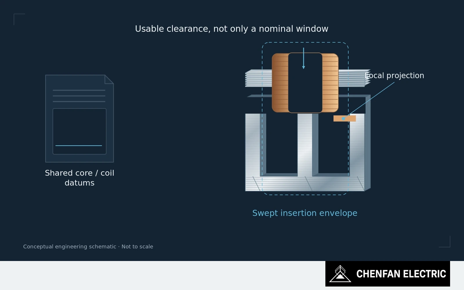
Define the usable envelope through assembly
Window height and width describe part of the available geometry. Winding installation also depends on insulation build, temporary handling allowances, clamp projections, local packet position and the route by which the coil reaches its final seat.
A clearance available in the final position may not exist during insertion. That distinction matters when a coil must pass a projecting feature, remain within an approved tilt limit or enter before another component is removed.
Define the usable envelope through the relevant manufacturing states. Include permanent insulation and the fixtures or protective elements that are present at each stage. Do not compare a bare-core opening with a finished-coil dimension and assume the difference is all available clearance.
Inspect the local restrictions and support state
The winding has tolerances too. Core and coil teams should work from a shared interface model, including the directions in which their variations reduce clearance. Nominal compatibility alone does not establish that the permitted combinations will assemble.
Check local restrictions rather than only the largest accessible opening. A packet projection or a clamp feature can control the insertion even when average window dimensions are satisfactory. The inspection should follow the constraining geometry.
State the support condition used for the check. A core held on a fixture may present a different opening from the released assembly, and the receiving factory needs to know which state the reported dimensions describe.
When an interference appears, forcing the winding into place is not a dimensional-control method. The issue needs an engineering disposition that protects the coil insulation and the intended core configuration. Removing material or shifting a limb can alter other interfaces that were already accepted.
Resolve the shared core-coil interface before manufacture
For a new supplier, a receiving-route trial or a suitable interface gauge can be more informative than another general dimension report. The validation method should represent the actual constraint rather than merely reproduce the nominal outline.
The RFQ should identify who owns this interface and which drawings define both sides. Without that agreement, core manufacture and coil manufacture can each be locally correct while final assembly remains unresolved.
Specify the window as usable space through an approved assembly route. That is the space production needs; the nominal rectangle is only its starting description.
Practical takeaway
Nominal window fit does not prove that a coil can reach its final position safely.
Chenfan Electric manufactures custom transformer cores according to customer drawings. Where applicable to the specified material and core design, agreed process controls include burr height below 0.02 mm and stacking factor above 97%. Measurement methods and acceptance conditions are defined for each order.