

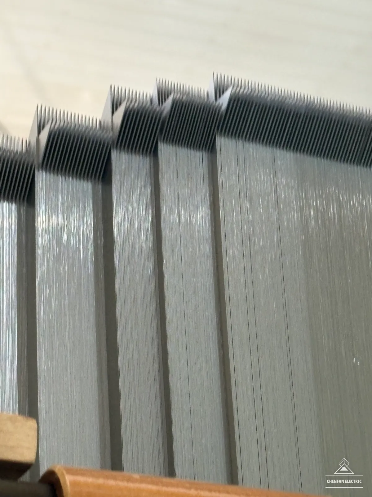
Joint geometry
Engineering Question
What must be controlled for a step-lap design to deliver repeatable core performance?
Key Data
- The manufacturing definition needs step sequence, lap length, joint gap and laminations per step.
- Loss and exciting-current results require a stated frequency, flux density and core configuration.
Technical Explanation
A step-lap joint distributes lamination ends across successive positions. Magnetic flux redistributes between the overlapping sheets near those ends, creating a local field that differs from the field in a straight limb. Joint geometry therefore affects magnetic behaviour as well as mechanical assembly.
The benefit depends on the material, core design and manufactured joint. A larger number of steps is not a universal guarantee of lower loss, and the smallest achievable gap is not a complete specification. Lap length, gap, layer grouping and sequence must be considered together.
The JFE patent reports different core-loss results when lap length changes while material thickness is held constant in its laboratory configuration. This supports evaluating joint geometry alongside material selection; its particular dimensions should not be copied into an unrelated drawing.
Correct cutting dimensions must be preserved through stacking. Misalignment, mixed packets or an incorrect sequence can change the intended joint. Mechanical restraint must hold the assembly without introducing uncontrolled local pressure.
Engineering Implications
- Define the complete joint schedule and check its reproduction through the stack.
- Assess loss and exciting current; agree separate noise evaluation when it is a project requirement.
Procurement Implications
- Ask for the joint definition behind the term “multi-step lap”.
- For cut or pre-stacked supply, agree identification and assembly instructions so the receiving factory can preserve the sequence.
What to Confirm Before Ordering
- Approved joint drawing, step count, grouping and sequence.
- Dimensional tolerances, inspection points and assembly responsibility.
- Test scope and acceptance requirements for the supplied format.
Technical Reference
Use the CRGO lamination order definition to specify joint sequence, piece identification and assembly responsibility.